


Description
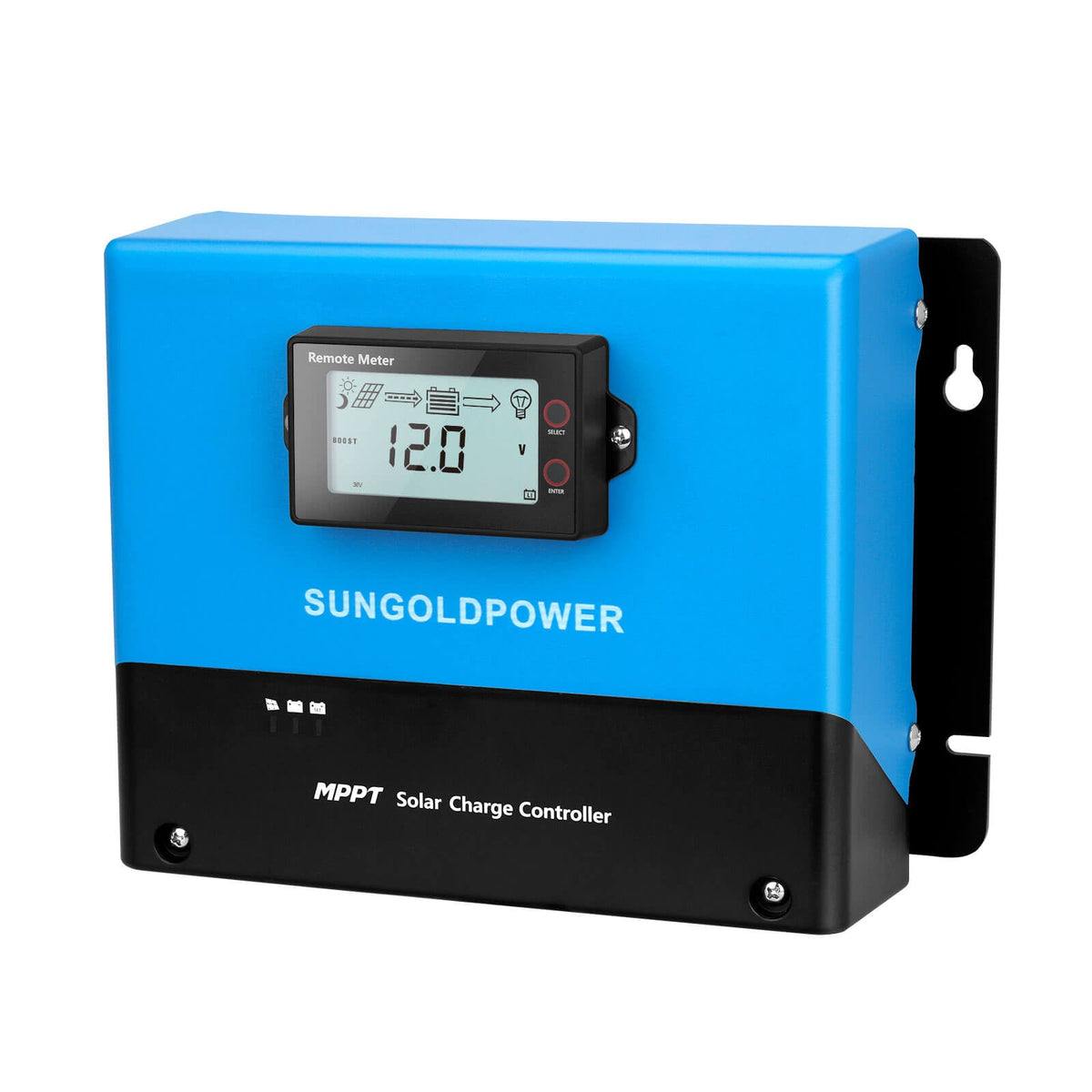
60 Amp MPPT Solar Charge Controller


The 60 Amp MPPT Solar Charge Controller from SunGoldPower is designed to efficiently manage solar energy charging for compatible battery systems. Using advanced PowerCatcher Maximum Power Point Tracking (MPPT) technology, the controller continuously adjusts to changing sunlight conditions to capture available solar power and transfer it to the connected battery bank.
Supporting automatic detection of 12V, 24V, and 48V DC battery systems, this controller is suitable for a variety of off-grid photovoltaic installations. It supports lithium batteries, sealed lead-acid batteries, AGM batteries, and customizable battery configurations, providing flexibility for different energy storage applications.
The controller features an LCD display, built-in Bluetooth monitoring, intelligent charging management, and multiple protection functions. Its parallel operation capability also supports system expansion when additional solar charging capacity is required.
Key Features


Specifications
- Rated Charging Current: 60A
- Supported Automatic System Voltages: 12V / 24V / 48V DC
- Battery Voltage Range: 9V–64V
- Adjustable Charging Current: 0–60A
- Solar Panel Power at 12V: 920W
- Solar Panel Power at 24V: 1840W
- Solar Panel Power at 48V: 3680W
- MPPT Tracking Efficiency: Up to 99.9%
- Charging Conversion Efficiency: Up to 98%
- No-Load Power Consumption: 0.54W
- Bluetooth: Built-in Bluetooth 4.0 BLE
- Communication Interfaces: TTL / Isolated RS485
- Communication Baud Rate: 9600
- Temperature Compensation Coefficient: -3mV/°C/2V (default, adjustable for lead-acid batteries)
- Lithium Battery Temperature Compensation: No temperature compensation
- Programmable Relay Output: DPST 10A/250VAC; 10A/30VDC
- Operating Temperature: -35°C to +65°C
- Temperature Derating Threshold: 40°C
- Maximum Operating Altitude: ≤3000 m
- Protection Rating: IP32
- Net Weight: 3.6 kg
- Conventional Controller Dimensions: 266 × 194 × 119 mm
- MC4 Controller Dimensions: 266 × 226 × 119 mm
- Installation Dimensions: 246 × 118 mm
- Mounting Hole Diameter: 5.5 mm

How to Use
Important: The controller operates at electrical voltages that may present shock and fire hazards. Read the complete user manual before installation. Electrical installation and maintenance must be performed by appropriately trained personnel.
Step 1: Select a Suitable Installation Location
-
Choose an indoor installation location.
-
Keep the controller away from direct sunlight and high temperatures.
-
Protect the controller from water exposure.
-
Ensure adequate ventilation around the equipment.
-
Leave at least 150 mm of clearance above and below the controller.
-
Avoid locations where airflow through the cooling system could be obstructed.
Step 2: Mount the Controller
-
Identify the controller's mounting positions.
-
Mark the four installation holes.
-
Drill suitable mounting holes at the marked positions.
-
Install the upper mounting screws.
-
Align the controller with the upper screws and position it securely.
-
Install and tighten the lower mounting screws.
-
Confirm that the controller is stable.
Step 3: Prepare the Electrical Connections
Before beginning electrical work:
-
Disconnect the photovoltaic array.
-
Open the battery fuse or breaker.
-
Confirm that the relevant electrical circuits are de-energized.
-
Prepare appropriately rated wiring.
-
Identify the positive and negative terminals.
-
Use insulated tools and suitable protective equipment.
The manual recommends appropriate fuses or circuit breakers at the photovoltaic and battery connections.
Step 4: Connect the Battery
The battery must be connected before the solar panels.
-
Confirm that the battery circuit remains disconnected.
-
Identify the positive and negative battery terminals.
-
Connect the battery cables according to the installation wiring diagram.
-
Follow the specified positive-before-negative connection sequence.
-
Verify the polarity of every connection.
-
Secure the terminals and cables.
Warning: Reversing the battery polarity may cause irreversible controller damage. Battery reverse-polarity wiring protection is not provided.
Step 5: Connect the Solar Panel Array
-
Confirm that the photovoltaic array remains isolated.
-
Identify the correct solar input terminals.
-
Connect the photovoltaic wiring according to the specified wiring diagram.
-
Verify correct polarity.
-
Confirm that the array specifications meet the controller's electrical requirements.
-
Secure all wiring connections.
Step 6: Inspect the Electrical Connections
Before applying power:
-
Check all battery connections.
-
Inspect all photovoltaic connections.
-
Verify positive and negative terminal polarity.
-
Confirm that electrical connections are secure.
-
Check grounding and applicable protective devices.
Step 7: Activate the Battery Connection
-
Close the battery fuse or breaker.
-
Observe the controller's LED indicator.
-
Confirm that the controller powers on normally.
If the indicator does not illuminate, disconnect the battery circuit immediately and inspect the wiring.
Step 8: Activate Solar Charging
-
Confirm that the battery connection is functioning normally.
-
Connect the solar panel array.
-
Ensure sufficient sunlight is available.
-
Observe the charging indicator.
-
Confirm that the controller begins charging.
During normal charging, the indicator should illuminate or flash.
Step 9: Configure the Battery Type
-
Access the battery settings through the controller.
-
Select the appropriate battery type.
-
Review the available charging parameters.
-
Confirm that the settings match the connected battery manufacturer's requirements.
-
Save the applicable configuration.
Supported battery types include lithium, sealed lead-acid, AGM, and customizable battery settings.
Step 10: Monitor System Performance
Use the LCD screen to view available information, including:
-
Battery voltage
-
Solar panel voltage
-
Charging current
-
Charging power
-
Charging status
-
Battery capacity
-
System voltage
-
Controller temperature
-
Error codes
Step 11: Use Bluetooth Monitoring
-
Install the compatible Solar APP on a supported mobile device.
-
Enable Bluetooth.
-
Open the application.
-
Connect to the controller using the application's supported procedure.
-
View available operating and charging information.
Step 12: Perform Routine Maintenance
-
Disconnect all controller power before maintenance.
-
Check that the ventilation and cooling areas are not obstructed.
-
Remove dirt or debris from the cooling surfaces.
-
Inspect wiring terminals for corrosion, discoloration, or overheating.
-
Check cables for damaged insulation.
-
Inspect the controller enclosure for damage.
-
Address abnormal operating conditions and error indications according to the user manual.
Do not disassemble or attempt unauthorized internal repairs.
Compatibility
Battery System Voltages: Automatically detects 12V, 24V, and 48V DC battery configurations.
Supported Battery Types:
-
Lithium batteries
-
Sealed lead-acid batteries
-
AGM batteries
-
Compatible customized battery configurations
Solar Photovoltaic Systems: Designed for compatible off-grid solar installations using photovoltaic panels and battery storage.
Parallel Controllers: Supports compatible parallel operation to increase charging capacity.
Bluetooth Monitoring: Supports compatible mobile monitoring applications using Bluetooth 4.0 BLE.
Communication: Supports TTL, isolated RS485, and compatible Modbus communication applications.
Battery charging parameters and solar array specifications must be verified before installation.
Product Support
Warranty
Warranty & Support
Price Match Guarantee
Payment & Security
Your payment information is processed securely. We do not store credit card details nor have access to your credit card information.