


Description
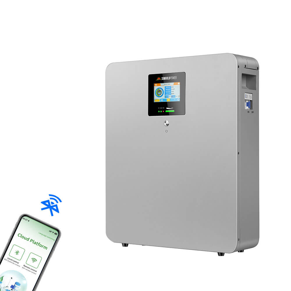
CoreX 5 Elite Wall Mounted 48V 100AH Residential Energy Storage Battery Pack Wi‑Fi & Bluetooth

.
The CoreX 5 Elite Wall Mounted 48V 100AH Residential Energy Storage Battery Pack Wi‑Fi & Bluetooth from SunGoldPower is designed to provide reliable residential energy storage for backup power, solar energy self-consumption, and household energy management. With a rated capacity of 100Ah and 5.12kWh of energy storage, it offers a practical solution for homes seeking greater flexibility in managing their electricity supply.
Built with premium EVE Energy lithium battery cells, the CoreX 5 Elite combines a smart Battery Management System (BMS), an integrated LCD display, and Wi-Fi and Bluetooth connectivity for battery monitoring. Its protective features help manage charging, discharging, temperature, and overall battery operating conditions.
Key Features


Specifications
- Product Configuration: 1P16S
- Battery Cell Manufacturer: EVE Energy
- Rated Capacity: 100Ah
- Rated Voltage: 51.2V
- Rated Energy: 5.12kWh
- Voltage Range: 43.2V–56.8V
- Charging Current Limit: 20A
- Standard Charge/Discharge Current: 50A
- Maximum Charge Current: 95A
- Maximum Discharge Current: 100A
- Recommended Temperature Range for Use: 10°C–45°C (50°F–113°F)
- Charging Operating Temperature: 4°C–55°C (39.2°F–131°F)
- Discharging Operating Temperature: -20°C–55°C (-4°F–131°F)
- Operating Humidity Range: 5–85% RH, no condensation
- Storage Temperature Within 1 Month: -20°C–45°C (-4°F–113°F)
- Storage Temperature Within 1 Year: 0°C–35°C (32°F–95°F)
- Storage Humidity: Less than 60% RH, no condensation
- Dimensions (D × W × T): (560±2) × (480±2) × (137±1) mm
- Approximate Dimensions: 22.05 × 18.9 × 5.39 inches
- Net Weight: 48±2 kg
- Approximate Net Weight: 105.82 lb
- Ingress Protection Rating: IP20
- Application Altitude: ≤3000 m (~9842.5 ft)
- Battery Monitoring: Integrated LCD display, Wi-Fi, and Bluetooth
- Inverter Communication Interfaces: CAN and RS485
- Additional Communication Interface: RS232
- Maximum Parallel Expansion: 15 units
- Wall-Mounting Hole Spacing: 328 mm horizontal × 300 mm vertical


How to Use
Important: Installation, commissioning, and electrical connections must be performed by qualified professional technicians. Read the complete user manual and follow all safety requirements before installation or operation.
Step 1: Inspect the Battery and Components
Before installation, inspect the packaging, battery housing, terminals, cables, and included accessories for damage or missing components.
Confirm that all required components are present and that the battery shows no visible damage.
Step 2: Select an Appropriate Installation Location
Install the battery indoors or in a professional rain shelter.
Choose a sturdy wall capable of supporting the battery's weight. Maintain sufficient clearance for ventilation, heat dissipation, and safe operation.
Keep the battery away from flammable materials, excessive heat, moisture, and direct sunlight.
Do not place objects underneath a wall-mounted battery.
Step 3: Install the Wall-Mounted Bracket
A qualified installer should:
-
Position the mounting bracket against a suitable wall.
-
Mark the mounting locations using the specified 328 mm horizontal and 300 mm vertical hole spacing.
-
Drill the required mounting holes with a diameter of 14 mm and a depth of at least 60 mm.
-
Secure the bracket using the supplied expansion bolts.
-
Apply a tightening torque of 12 N·m.
-
Lift the battery into position and hang it securely on the bracket.
-
Confirm that the battery is properly mounted.
Step 4: Connect the Battery to the Inverter
A qualified technician must connect the battery's positive and negative power terminals to the corresponding inverter terminals using the appropriate power cables.
Verify terminal polarity and connector compatibility before completing the connections.
Step 5: Connect Communication Cables
Connect the inverter communication port to the battery's corresponding CAN or RS485 communication interface.
Confirm that the communication cable pin assignments match the compatible inverter's requirements.
Step 6: Complete the Grounding Connection
The installer must connect the battery grounding point to the grounding network.
The user manual specifies an M5 × 12 grounding screw with a tightening torque of 3.5 N·m.
Step 7: Inspect the Completed Installation
Before startup, a qualified technician must verify the power connections, communication connections, grounding, mounting stability, and applicable electrical safety requirements.
Step 8: Power On the Battery
For a single battery installation:
-
Confirm that all wiring connections are correct.
-
Press the power button on the battery's front panel.
-
Allow the LED indicators to illuminate sequentially.
-
Confirm that the battery status indicators display normal operating conditions.
For multiple batteries connected in parallel, follow the master-and-slave startup sequence specified in the user manual.
Step 9: Monitor Battery Performance
Use the integrated LCD display to view the battery's:
-
State of charge (SOC)
-
Voltage
-
Current
-
Capacity
-
Alarm information
-
Protection status
Bluetooth and Wi-Fi connectivity also support battery monitoring through the applicable mobile application.
Step 10: Power Off the Battery
For a single battery installation:
-
Press the front-panel power button to turn off the battery.
-
Confirm that the LED indicators have turned off.
-
Follow the user manual's procedure for disconnecting external power and communication cables when required.
For systems with multiple batteries connected in parallel, follow the separate shutdown sequence provided in the user manual.
Compatibility
- Inverter Integration: Supports communication with compatible inverter systems using CAN or RS485 interfaces.
- Inverter Brand Compatibility: Designed to communicate with most major inverter brands, subject to supported communication protocols and electrical compatibility.
- Parallel Battery Systems: Supports up to 15 battery units connected in parallel.
- Residential Solar Systems: Suitable for integration into compatible solar photovoltaic energy storage systems.
- Compatibility must be confirmed against the specific inverter's electrical specifications and communication requirements before installation.
Included
The official user manual identifies the following package contents per battery pack:
-
1 × CoreX 5 Elite battery pack
-
1 × Wall-mounted bracket
-
4 × Expansion bolts
-
4 × Rubber feet with bolts
-
1 × White U-shaped metal edge protection strip (0.6 m)
-
1 × Positive output power cable
-
1 × Negative output power cable
-
1 × Positive parallel power cable
-
1 × Negative parallel power cable
-
1 × Pack-inverter communication cable
-
1 × Pack parallel communication cable
-
Product factory test report
-
Product certificate
-
User manual
Product Support
Warranty
Warranty & Support
Price Match Guarantee
Payment & Security
Your payment information is processed securely. We do not store credit card details nor have access to your credit card information.