


Description
CoreX 5 Pro Server Rack 48V 100AH Residential Energy Storage Battery Pack Wi‑Fi & Bluetooth

 .
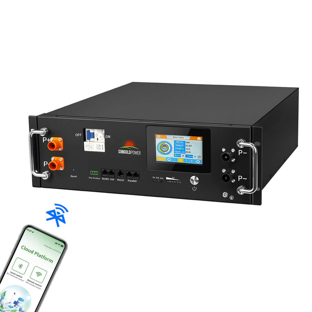
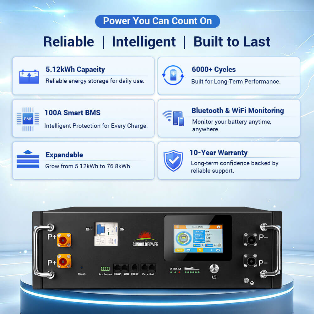
The CoreX 5 Pro Server Rack 48V 100AH Residential Energy Storage Battery Pack Wi‑Fi & Bluetooth from SunGoldPower is a residential energy storage solution designed for backup electricity, solar energy self-consumption, and household energy management. With a rated capacity of 100Ah and 5.12kWh of energy storage, it provides a flexible way to store energy for compatible residential power systems.
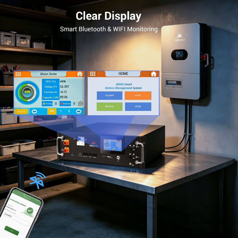
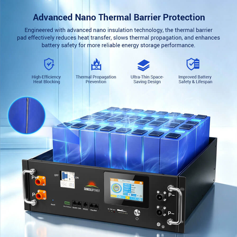
Featuring a server-rack-style design, an integrated Battery Management System (BMS), and Wi-Fi and Bluetooth connectivity, the CoreX 5 Pro offers convenient access to battery performance information. Its monitoring and protection functions help manage charging, discharging, temperature, and overall battery health.
Key Features


Specifications
- Battery Configuration: 1P16S
- Rated Capacity: 100Ah
- Rated Voltage: 51.2V
- Rated Energy: 5.12kWh
- Voltage Range: 43.2V–56.8V
- Charging Current Limit: 20A
- Standard Charge/Discharge Current: 50A
- Maximum Charge Current: 95A
- Maximum Discharge Current: 100A
- Recommended Temperature Range for Use: 10°C–45°C (50°F–113°F)
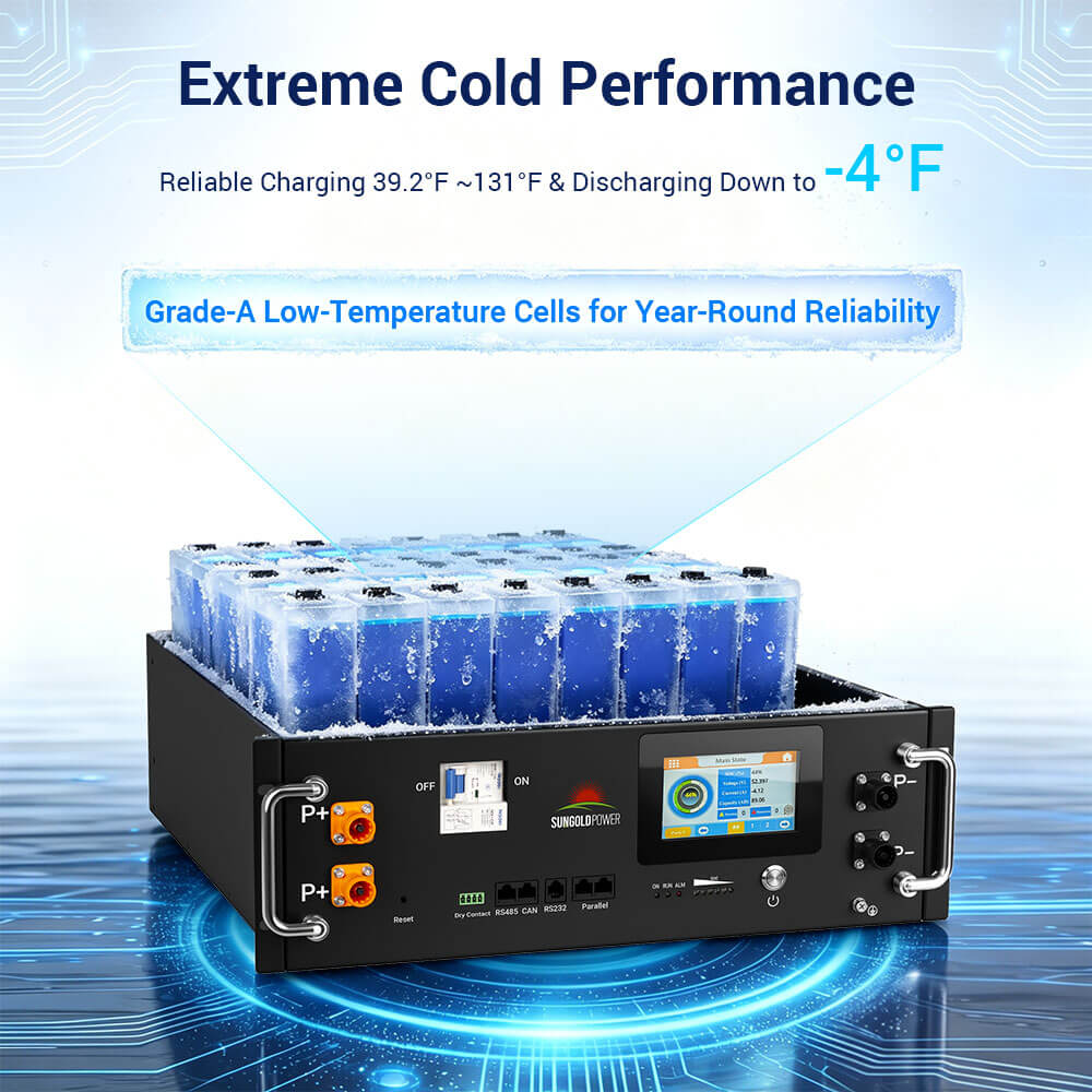
- Charging Operating Temperature: 4°C–55°C (39.2°F–131°F)
- Discharging Operating Temperature: -20°C–55°C (-4°F–131°F)
- Operating Humidity Range: 5–85% RH, no condensation
- Storage Temperature Within 1 Month: -20°C–45°C (-4°F–113°F)
- Storage Temperature Within 1 Year: 0°C–35°C (32°F–95°F)
- Storage Humidity: Less than 60% RH, no condensation
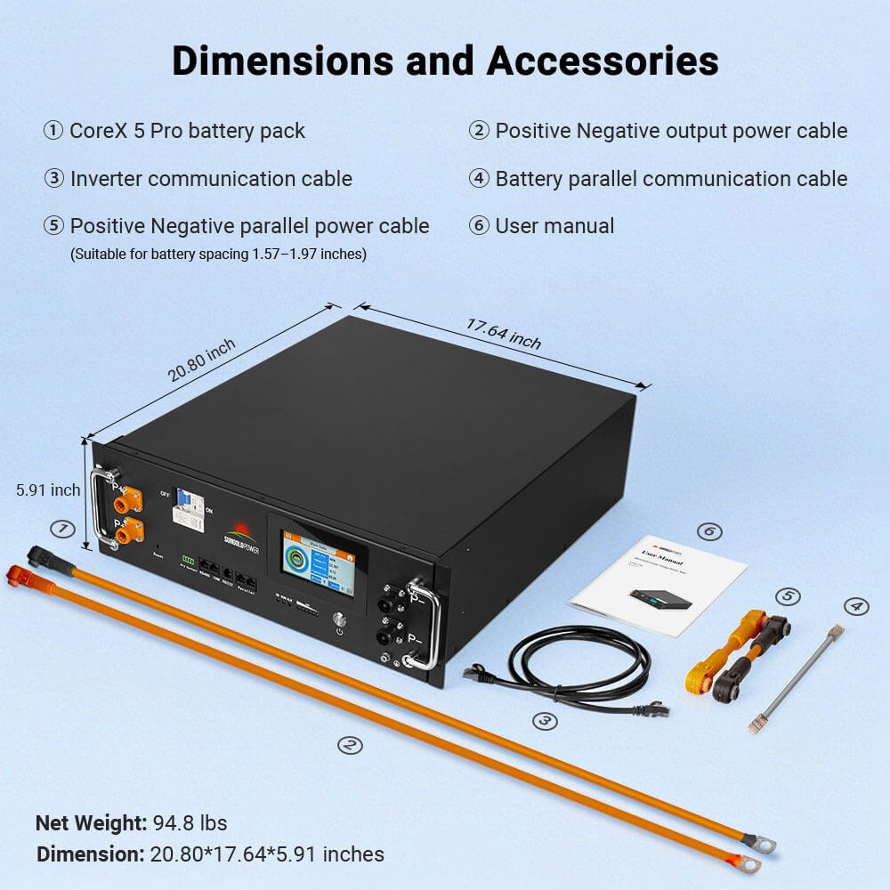
- Battery Dimensions (D × W × T): (510±2) × (442±2) × (130.5±1) mm
- Battery Dimensions in Inches: 20.08 × 17.4 × 5.14 inches
- Net Weight: 43±2 kg
- Net Weight in Pounds: 94.8 lb
- Ingress Protection Rating: IP20
- Application Altitude: ≤3000 m
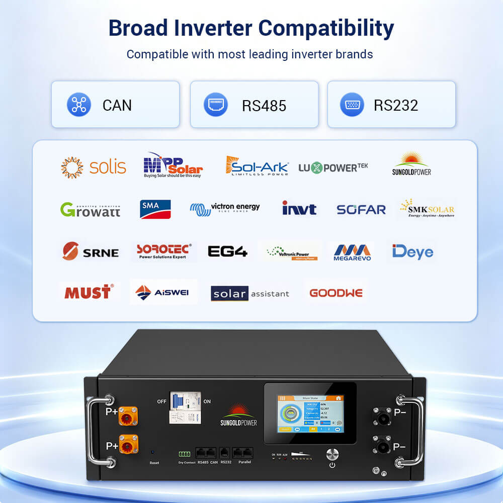
- Communication Interfaces: CAN, RS485, RS232
- Battery Monitoring: LCD display, Wi-Fi, Bluetooth
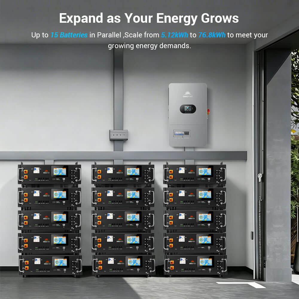
- Maximum Parallel Connection: 15 battery packs
- Grounding Point: M5 bolt
- Grounding Bolt Torque: 3.5 N·m
- Required System Grounding Resistance: Less than 4Ω
- Recommended Grounding Cable Cross-Sectional Area: ≥10 mm²
- Minimum Clearance Between Parallel Battery Enclosures: 10 cm


How to Use
Important: Installation, commissioning, maintenance, and electrical connections must be performed by qualified professional technicians. Carefully read the complete user manual before installation and operation.
Step 1: Inspect the Battery and Package Contents
Before installation:
- Inspect the packaging for damage.
- Confirm that all listed package components are included.
- Examine the battery enclosure for deformation, damage, or loose components.
- Check the terminals and communication connections for dirt, moisture, or corrosion.
- Inspect the power and communication cables for damaged insulation or loose connections.
Do not proceed if the battery or its components show signs of damage.
Step 2: Prepare the Installation Location
- Select a clean, stable, and dry installation area.
- The battery must be installed indoors or within a professional rain shelter.
- The installation surface must meet the equipment's weight-bearing and fire-safety requirements.
- Provide adequate space for ventilation, heat dissipation, maintenance, and safe operation.
- Keep the battery away from flammable materials, corrosive substances, heat sources, and direct sunlight.
Step 3: Position and Secure the Battery
- A qualified technician must install the battery in accordance with the manufacturer's confirmed orientation requirements.
- For rack installations, ensure the supporting structure is suitable for the battery enclosure and installation environment.
- Verify that the battery is stable and securely positioned before making electrical connections.
Step 4: Complete the Grounding Connection
Each battery enclosure includes a grounding point.
A qualified technician must:
- Connect the battery enclosure to the grounding network.
- Use the designated M5 grounding point.
- Apply the specified tightening torque of 3.5 N·m.
- Verify the required grounding resistance.
For rack installations, connect the rack to the grounding grid before grounding the individual battery enclosures to the rack.
Step 5: Connect the Power Cables
- Before making electrical connections, ensure the equipment switches are in the OFF position.
- The installer must verify electrical safety and grounding before working with terminals or conductors.
- Connect the battery's negative power terminal (P-) to the corresponding inverter negative terminal.
- Connect the positive power terminal (P+) to the corresponding inverter positive terminal.
- Confirm that connector colors and terminal polarities match.
Step 6: Connect the Communication Cable
- Select the appropriate CAN or RS485 communication interface for the compatible inverter.
- Connect the battery and inverter communication ports using the appropriate communication cable.
- Verify that the communication pin assignments match the inverter's requirements.
Step 7: Configure Multiple Batteries if Applicable
When connecting multiple battery packs in parallel:
- Position the battery packs with at least 10 cm of clearance between adjacent enclosures.
- Connect the parallel power cables using the applicable wiring configuration.
- Connect the parallel communication interfaces according to the system design.
- Confirm the correct master-and-slave configuration.
- Do not exceed 15 battery packs connected in parallel.
For systems with a maximum current exceeding 100A, the installation manual requires a busbar connection arrangement.
Do not connect battery packs in series.
Step 8: Perform the Post-Installation Inspection
Before startup, the technician must confirm:
- The installation environment is suitable.
- The battery enclosure is undamaged.
- The equipment is securely installed.
- The power and communication cables are correctly connected.
- Grounding connections are secure.
- Electrical protection and insulation requirements have been satisfied.
Step 9: Power On the Battery
For single-battery operation:
- Confirm that the battery-to-inverter wiring connections are correct.
- Press the power button on the front panel.
- Observe the LED indicators as they illuminate sequentially.
- Confirm that the battery displays normal operating status.
For multiple batteries connected in parallel, power on the master battery first, followed by the slave batteries in the sequence specified in the user manual.
Step 10: Monitor Battery Status
Use the battery's monitoring interface to check:
- State of charge (SOC)
- State of health (SOH)
- Battery voltage
- Battery current
- Battery capacity
- Operating temperature
- Alarm information
- Protection status
The battery also supports monitoring through Bluetooth and Wi-Fi using the applicable mobile application.
Step 11: Use Bluetooth or Wi-Fi Monitoring
- Download the compatible battery monitoring application using the instructions provided in the user manual.
- Open the application.
- Grant the necessary permissions requested by the application.
- Select local Bluetooth control or remote Wi-Fi control.
- Follow the application instructions to connect the battery.
- Access the available battery information and monitoring functions.
Step 12: Power Off the Battery
For single-battery operation:
- Press the front-panel power button to turn off the battery.
- Confirm that the LED indicators have turned off.
- Follow the specified procedure for disconnecting external power and communication cables when required.
For multiple batteries connected in parallel, follow the separate shutdown procedure provided in the user manual.

Compatibility
- Inverter Communication: Supports compatible inverter communication through CAN and RS485 interfaces.
- Battery Monitoring: Supports Bluetooth and Wi-Fi communication with the applicable battery monitoring application.
- Parallel Battery Connections: Supports up to 15 battery packs connected in parallel.
- Solar Energy Systems: Designed for integration with compatible photovoltaic energy storage systems.
- Residential Backup Applications: Supports emergency backup electricity when properly integrated into a compatible power system.
- Electrical specifications and communication protocol compatibility must be verified before connecting the battery to an inverter.

Included
The official packing list identifies the following contents per battery pack:
-
1 × CoreX 5 Pro battery pack
-
1 × Positive output power cable
-
1 × Negative output power cable
-
1 × Positive parallel power cable
-
1 × Negative parallel power cable
-
1 × Pack-inverter communication cable
-
1 × Pack parallel communication cable
-
Product factory test report
-
Product certificate
-
User manual
Product Support
Warranty
Warranty & Support
Price Match Guarantee
Payment & Security
Your payment information is processed securely. We do not store credit card details nor have access to your credit card information.